
제품소개
차별화된 기술력과 창조적인 사고로 더 큰 도약을 꿈꿉니다.
비례제어식 콘트롤밸브
- Home > 제품소개 > 피스톤식 콘트롤밸브 > DPCV-4F / 4S
제품소개
SPCV-1
Pneumatic Diaphragm Globe Control Valve
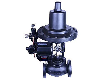
- 특 징
- DIAPHRAGM식 GLOBEVALVE로 구조가 간단, 견고하며 STEM의 PACKING은 특수오링으로 제작되고, DIAPHRAGM은 N.B.R에 특수가공된 이중포직을 삽입하여장기간 사용해도 탁월한 성능과 내구력을 유지함.
- 정밀한 바란스 구조에 의한 포트를 선정하여 유량을정밀하게 제어할수 있다.
- 종/횡 어떤 조건에서도 사용이 가능하다.
- VALVE BODY와 구동부를 연결하는 YOKE부위에는 특수 TELONSEALING과 VITON SEALING축에 삽입하여 작동횟수에 관계없이 탁월한 성능을 유지시킨다
- 개폐는 중앙에 표지판에 의해 육안으로 확인할 수 있다.
- 주의사항
- 운반이나 취급, 혹은 사용중에 제품에 과도한 진동, 충격을 주면 고장의 원인이 될 수 있다.
- 사양온도범위를 초과하여 사용하면 고장의 원인이 될수 있다.
- 사용하지 않는 배관연결 구멍에는 항상 BlindPlug를 사용해야 한다.
- 포지셔너를 사용하지 않고 실외에 장기간 방치할 경우에는비가 새어들지않도록 본체 덮개를 씌워두어야한다. 또한 고온 다습한 환경이라면 내부에 응축수가 고이지 않도록 조치해야 한다.
- 치 수
| SIZE | 15A~25A(½"~¾") | 25A(1") | 32A(1¼") | 40A(1½") | 50A(2") | 65A(2½") | 80A(3") | 100A(4") | 125A(5") | 150A(6") |
|---|---|---|---|---|---|---|---|---|---|---|
| L | 185 | 185 | 205 | 205 | 220 | 265 | 280 | 330 | 370 | 412 |
| H1 | 80 | 85 | 90 | 95 | 105 | 110 | 110 | 140 | 170 | 190 |
| H2 | . | . | . | . | . | . | . | . | . | . |
| CV | 5 | 8 | 14 | 22 | 37 | 62 | 95 | 150 | 237 | 330 |
| SIZE | 15A~25A (½"~¾") |
25A(1") | 32A (1¼") |
40A (1½") |
50A (2") |
65A (2½") |
80A( 3") |
100A (4") |
125A (5") |
150A (6") |
|---|---|---|---|---|---|---|---|---|---|---|
| L | 185 | 185 | 205 | 205 | 220 | 265 | 280 | 330 | 370 | 412 |
| H1 | 80 | 85 | 90 | 95 | 105 | 110 | 110 | 140 | 170 | 190 |
| H2 | . | . | . | . | . | . | . | . | . | . |
| CV | 5 | 8 | 14 | 22 | 37 | 62 | 95 | 150 | 237 | 330 |
- 사 양
| 적용 유체 |
사용 압력 |
사용 온도 |
접속 방식 |
재질 | 구동형식 | 악세사리 | 구동부 | |
|---|---|---|---|---|---|---|---|---|
| WATER AIR STEAM |
MAX 10kgf/㎠g MAX 20kgf/㎠g MAX 30kgf/㎠g |
MAX 80℃ |
KS 10K/20K /30K RF/FF FLANGE, ANSI 150#/ 300#/600# RF FLANGE |
BODY GCD450, SCPH2, SCS13 TRIM STS PTFE |
단동식 |
E/P Positioner Sol. Valve, Air Regulator, Air Set. |
다이야 후렘식 |
|
– 온도 80℃ 이상은 주문생산
– ANSI, DIN 주문생산
– STS316, STS316L은 주문생산
– CV CALCULATION
- CV CALCULATION
[①,② : IEC / ANS / ISA-S75.01, ③~⑥ : FCI62-1]
- CONTROL VALVE SEAT LEAKAGE CLASSIFICATION
[FCI 70-2]
| Leakage Class Designation |
Maxinum Leakage Allowable |
Test medium |
Test pressures |
Test procedures Required for Establishing ration |
|---|---|---|---|---|
| Ⅰ | - | - | - | Not test required provided user and supplier so agree |
| Ⅱ | 0.5% of rated capacity | Air or water at 50-125° F (10-52℃) |
45-60 psig or max opreation differential, whichever os lower |
Pressure applied to valve inlet, with outlet open to atmosphere or connected to a low head loss measuring device full normal closing thrust provided by actuator |
| Ⅲ | 0.1% of rated capacity | As above | As above | As above |
| Ⅳ | 0.01% of rated capacity | As above | As above | As above |
| Ⅴ | 0.0005㎖ per minute of water per inch of port diameter per psi differential |
Water at 50-125° F (10-52℃) |
Max. service pressure drop across valve plug, not to exceed ANSI body rating. (100psi pressure drop minimum) |
Pressure applied to valve inlet, |
| Ⅵ | Not to exceed amounts shown in following table based on port diameter |
Air or Nitrogen at 50-125° F (10-52℃) |
50 psig or max. Rated differential pressure across valve plug. Whichever if lower. |
Actuator should be adjusted to operating conditions specific with full normal closing thrust applied to valve plug seat. Allow time for leakage flow to stabilize & use suitable measuring device. |
| Nominal prot diameter | Leakage factor | ||
|---|---|---|---|
| Inches(B) | Millimeters(mm) | ㎖ per Minute | Bubbles per minute |
| 1" | 25 | 0.15 | 1 |
| 1½" | 38 | 0.30 | 2 |
| 2" | 51 | 0.45 | 3 |
| 2½" | 64 | 0.60 | 4 |
| 3" | 76 | 0.90 | 6 |
| 4" | 102 | 1.70 | 11 |
| 6" | 152 | 4.00 | 27 |
| 8" | 203 | 6.75 | 45 |
Bubble per minute as tabulated are an easily measured suggestedalternative based on suitable calibrated measuring device such as a ¼”O.D.x0.032″ wall tube submerged in water to a depth of ⅛” to ¼”. The tube end shall be cut square and smooth with on chamfersor burrs and the tube axis shall be perpendicular to the surface of the water. Otherapparatus may be constructed and the number of bubbles per minute may vary from these shown. Aslong as they correctly indicate the flow in miper minute.